
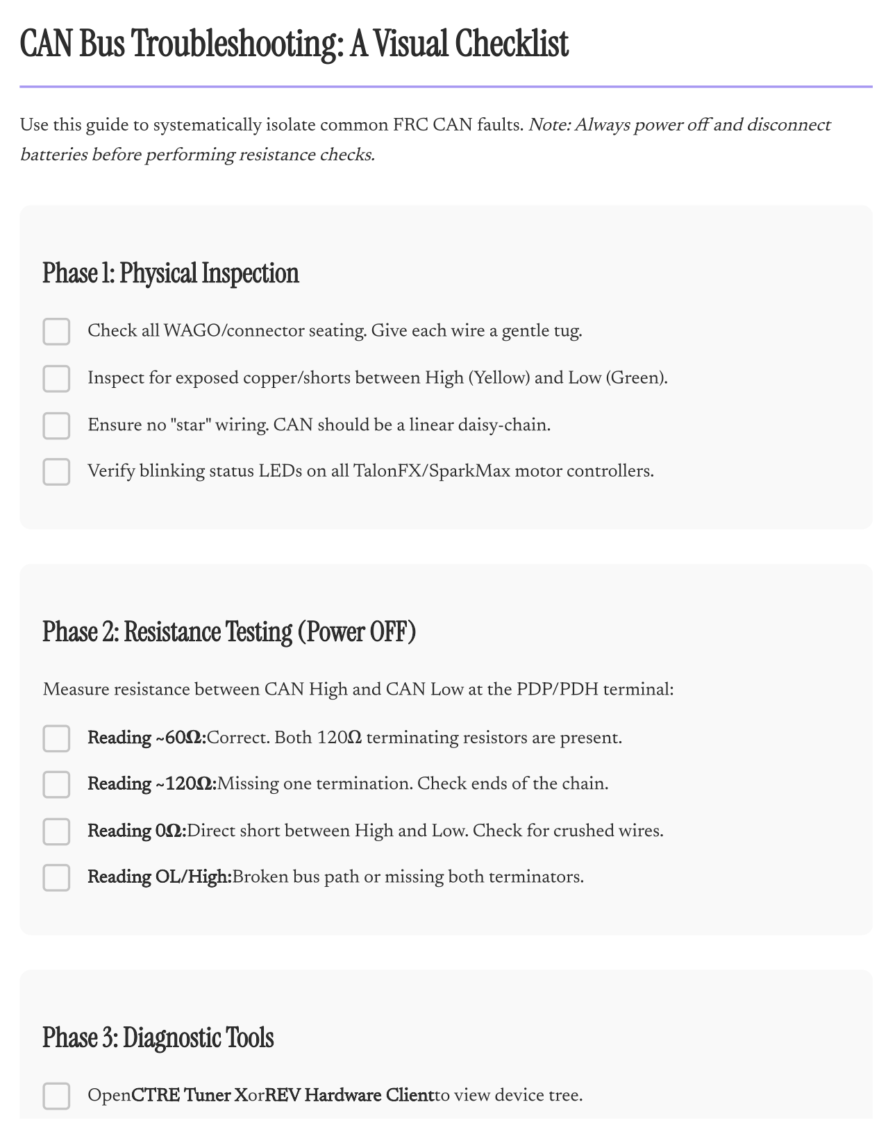
Use this guide to systematically isolate common FRC CAN faults. This resource provides a three-phase approach to debugging your robot’s communication network:
Phase 1: Physical Inspection — Procedures to verify connector seating, identify shorts, and ensure your bus follows the required linear daisy-chain topology.
Phase 2: Resistance Testing — A step-by-step method to measure resistance at the PDP/PDH terminal, helping you quickly distinguish between a healthy bus (~60Ω), a missing terminator (~120Ω), a direct short (0Ω), or a broken path (OL/High).
Phase 3: Diagnostic Tools — Guidelines for using CTRE Tuner X and the REV Hardware Client to audit your device tree and monitor CAN utilization percentages via the Driver Station.
Note: Always power off and disconnect batteries before performing resistance checks.